SiWx917 Quick Start
Build, flash, and run your first TuyaOpen application on a SiWx917 dev kit.
Prerequisites
- Completed Environment Setup
- Basic familiarity with C development and serial terminals
Requirements
- A SiWx917 dev kit (
SIWX917_AI_DEV_KITorBRD2605A) - A J-Link debug probe (SWD flashing), or a USB-serial adapter (ISP serial flashing)
- The USB data cable for the probe / adapter
- About 5 GB of free disk (the first build pulls the Simplicity SDK and SLC)
- A Wi-Fi network (2.4 GHz)
If your application uses Tuya Cloud features (remote control, AI Agent, OTA), you also need a Tuya Cloud license key. Local-only projects (GPIO, UART, display demos) do not need one.
Steps
1. Clone TuyaOpen and set up the environment
git clone https://github.com/tuya/TuyaOpen.git
cd TuyaOpen
git submodule update --init
Activate the TuyaOpen environment:
. ./export.sh
SiWx917 is an officially supported platform: it is listed in platform/platform_config.yaml, and its board support lives in boards/SIWX917/. The first SiWx917 build downloads Silicon Labs SLC and Simplicity Commander into platform/SIWX917/tools/.
2. Choose a project to build
For your first build, use the switch demo (a simple cloud-connected switch):
cd apps/tuya_cloud/switch_demo
3. Select the board config
tos.py config choice
Pick SIWX917_AI_DEV_KIT or BRD2605A.
If you previously built for a different board or changed peripheral Kconfig, run tos.py clean first — otherwise SLC skips generation; see Build.
4. Build
tos.py build
Firmware artifacts land in the app's dist/ and .build/ directories. The first build also pulls the Silicon Labs SDKs and tools; see the overview.
5. Flash the firmware
tos.py flash
Two prompts appear in order:
- Channel:
swd(J-Link probe) orserial(ISP UART). - Target:
M4 ONLY(your application),TA ONLY(NWP radio firmware), orTA + M4(both).
Wiring for the two channels:
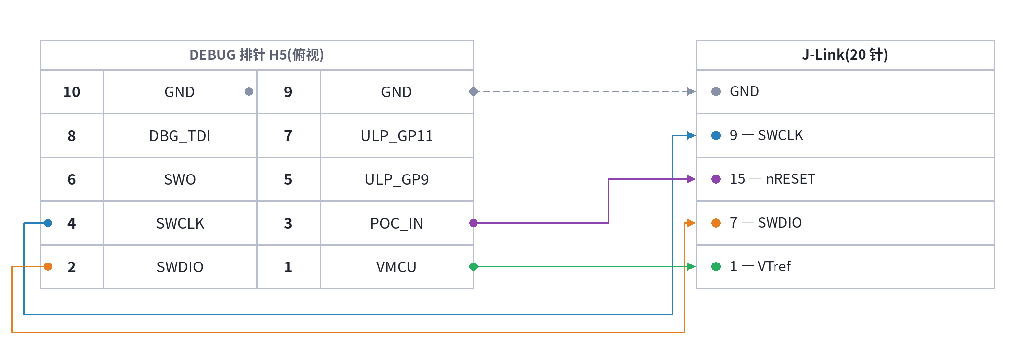
AI dev kit: external J-Link to the DEBUG header (H5); for the serial (ISP) channel, see Flash over ISP with a serial adapter below.
Flash over ISP with a serial adapter
For the serial channel, wire the USB-serial adapter to the module header H2:
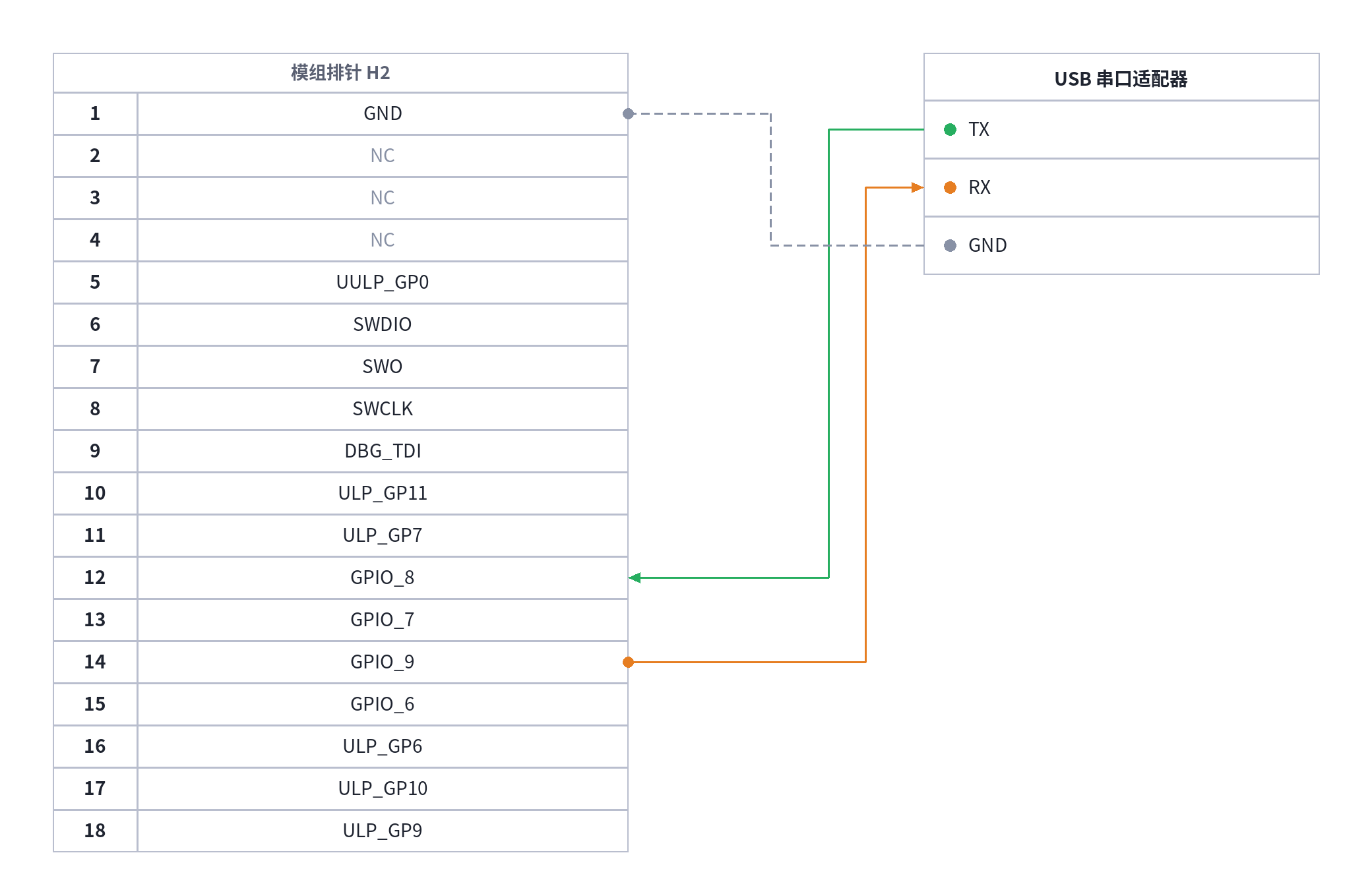
Before flashing, guide the chip into ISP mode: hold the on-board ISP button, tap RESET, then release ISP — the chip samples GPIO_34 (SWO, H5-6 / H2-7) as reset is released, and a low level there enters the ROM bootloader. Once in, the port runs 115200 8N1: send Ctrl+\ to wake it, then press U to print the flash menu.
This ISP UART is a different pair from the log ULP UART; the two cannot share wires.
The radio runs its own firmware (TA), separate from your application, and the application cannot start without it. Writing TA erases the radio's flash first; an interrupted write can leave the device in need of recovery — so write it only when the device actually reports having none. tos.py flash reads the device's TA version and prompts you when it is missing.

BRD2605A: one USB Type-C cable covers flashing and logs — no wiring needed.
6. Open the log
The application log leaves on the ULP UART.
- BRD2605A: the log lands on the on-board J-Link VCOM;
tos.py monitorfinds it with no wiring. - External probe (AI dev kit): wire the USB-serial adapter to the same DEBUG header (H5):
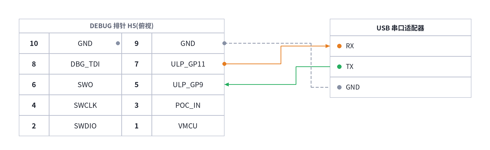
RX and GND alone are enough to read the log. This UART is a different pair from the ISP UART used for serial flashing — the two cannot share wires.
tos.py monitor
7. Provision and verify
Provision the device over BLE with the Tuya Smart app — on SiWx917, BLE is the only available provisioning method. Details in Device Network Configuration.
Expected result
Once Wi-Fi connects, the switch demo starts reporting to the cloud: you can toggle it from the Tuya Smart app panel, and tos.py monitor shows the matching DP reports and commands.
Related documentation
- SiWx917 Overview
- Equipment Authorization: Burn the license key before connecting to Tuya Cloud.
- Device Network Configuration: Pairing over BLE in detail.